Electricity AS Physics

?

Charge, Current and Potential Difference

Charge- The amount of charge that passes in 1 second when the current is 1 Ampere

  • Charge is measured in Coulombs (C). A single electron carries a charge of 1.6 x 10⁻¹⁹ C
  • An electron always has a negative charge of -1.6 x 10⁻¹⁹ coulombs. Protons have an equal amount of positive charge. One coulomb is equal to the charge on 6.25 x 10¹⁸ electrons

Current-  is the rate of flow of charge.

  • Current is measured in amperes (A).
  • A current of 1 A means that 1 coulomb of charge flows past a point in a circuit every second.   (1 A = 1 C s-1) Current is measured in a circuit using an ammeter

Potential Difference- is the work done per unit charge.

  • A potential difference of 1 V means that 1 joule of work is done per coulomb of charge. ( 1 V = 1 J C-1) Potential difference in a circuit is measured using a voltmeter which is placed in parallel with the component of interest in the circuit.
1 of 12

Drift Velocity

I = vAnq , Where:

  • I = current (amps, A)
  • v = drift velocity (m/s)
  • A = cross-sectional area of the conductor (m2)
  • n = charge density (m-3) This is the number of charge carriers that can move per m3
  • q = charge on each charge carrier (coulombs, c)

If the cross-sectional area of a wire is A and the number of charge carriers per m3 is n, then: Number of charge carriers per metre of wire = An

If each charge carrier is travelling at speed v (m/s) along the wire, then: Number of charge carriers passing a point in the wire per second = vAn

If each charge carrier has a charge q, then: The amount of charge passing along the wire per second (i.e. the current, I) = vAnq

2 of 12

Resistance

  • The Resistance of a component decides how much voltage will be dropped across it for a particular current.
  • Resistance is measured in Ohms (Ω). According to Ohm's Law, voltage is the product of current and resistance.
  • Everything has Resistance, because everything has opposition to the flow of Electric Charge.

Voltage = Current x Resistance

3 of 12

Resistivity

Resistivity is 

  • Resistivity is given the symbol ρ and is measured in Ohm Meters (Ωm, or Kgm3s-3A-2 in base units).
  • For example, copper has a Resistivity of 1.68 ×10⁻⁸ Ωm, and Germanium 4.6 ×10⁻¹ Ωm.
  • The Resistance of a material of Resistivity ρ, length l and cross-sectional area A is calculated by the formula:

4 of 12

I-V Characterisitcs

(http://h2physics.org/wp-content/uploads/2010/03/i-vgraphs.jpg)

5 of 12

Electrical Power

Power- is the rate of transfer of energy e.g rate of doing work

P=VI or P=V^2/R or P=I^2R

6 of 12

emf and internal resistance

e.m.f.- is the energy provided by a cell or battery per coulomb of charge passing through it,

it is measured in volts (V). It is equal to the potential difference across the terminals of the cell when no current is flowing.

e=E/Q

  • e = electromotive force in volts, V
  • E = energy in joules, J
  • Q = charge in coulombs, C

e = I x (R+r)

  • e = electromotive force in volts, V
  • I = current in amperes, A
  • R = resistance of the load in the circuit in ohms, W
  • r = internal resistance of the cell in ohms, W
7 of 12

e.m.f cont..

(http://physicsnet.co.uk/wp-content/uploads/2010/08/emf-straight-line.jpg)emf graph (http://physicsnet.co.uk/wp-content/uploads/2010/08/emf-graph.jpg)

8 of 12

Conservation of Charge

Kirchoffs 1st law- The total current entering a junction = the total current leaving it. AKA

  • Total in = Total Out
9 of 12

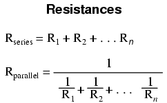
Proving Restors in Series

IN SERIES V=IR

(http://www.electrical4u.com/images/march16/1463495197.GIF)

10 of 12

Proving Restores in Parallel

(http://www.electrical4u.com/images/march16/1463494785.GIF)                 (http://www.electrical4u.com/images/march16/1463494620.GIF)

(http://electrical4u.com/electrical/basic-electrical-equation/resistances-in-series-and-resistances-in-parallel-1.gif)

(http://electrical4u.com/electrical/basic-electrical-equation/resistances-in-series-and-resistances-in-parallel-2.gif)

11 of 12

Potential Dividers

Potential divider is a simple circuit that uses resisters to supply a variable potential difference.

They can be used as audio volume controls, to control the temperature in a freezer or monitor changes in light in a room.

Two resistors divide up the potential difference supplied to them from a cell. The proportion of the available p.d. that the two resistors get depends on there resistance values.

  • Vin = p.d. supplied by the cell
  • Vout = p.d. across the resistor of interest
  • R1 = resistance of resistor of interest R1
  • R2= resistance of resistor R2

Potential divider diagram 1 (http://physicsnet.co.uk/wp-content/uploads/2010/08/potential-divider.jpg)(http://physicsnet.co.uk/wp-content/uploads/2010/08/potential-divider-equation.jpg)

12 of 12

Comments

No comments have yet been made

Similar Physics resources:

See all Physics resources »See all Electricity resources »