metal manufacturing processes
- Created by: annietaylor15
- Created on: 20-05-19 14:36
sand casting
Pouring molton metal into a prepared cavity in a sand mould and allowing it to solidify.
Investment casting
A shell mould is built up around a wax pattern that can be melted away leaving a cavity which is then filled with molten metal. Multiple wax patterns are assembled into a pattern 'tree' which is dipped in refacturyslurry to coat it and form a skin. This is dried and the process of dipping in slurry and drying is repeated until a robust shell is achieved. The shell is then placed in an oven to melt out the wax. This results in a hollow mould that can be filled with the molten metal
high pressure die casting
Die Casting is the process of forcing molten metal under high pressure into the cavities of steel moulds. The moulds are called diesand are made from steel. Die casting is used to produce non-ferrous metal parts ranging from gold putter heads to car engine blocks.
The process lends itself to making metal parts that:
1. must be precise (± 0.05mm)
2. must have a very smooth surface that can be bright plated without prior polishing and buffing
3. have sections as thin as 1mm
4. must be produced much more economically than parts machined from solid
gravity die casting
This is a low-tech process is well suited for the batch production of simple forms without undercuts. mazak, an alloy of zinc and aluminium, is first melted in a crucible furnace. Molten metal is then poured by ladle into a open steel mould where it is allowed to cool and solidify. The mould is then turned upside down and tapped with a hammer to release the finished casting.
CNC Milling
The casting is held firmly in a fixture bolted to the milling machine table (left). The milling machine is programmed so that two identical cuts are made each time the program is run. The machine head in this example moves vertically up and down to position the rotating milling cutter for depth of cut. The table holding the workpiece then moves horizontally against the milling cutter.
The advantages of using CNC machines are speed, accuracy and the fact that they don't require highly skilled operators to run them once they've been set up and programmed. The high cost of buying CNC milling machines makes this process suitable for large batches of components rather than one-offs.
CNC Lathework
A lathe machine utilizes CNC technology, which is the acronym for Computer Numerical Control. This machine creates customized products, including shafts for the automotive industry, wood legs for the furniture industry, household products, and more, using workpieces made of metal, plastic, and wood.
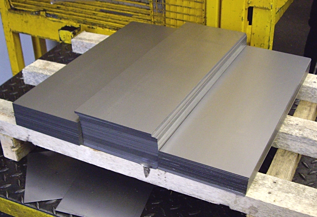
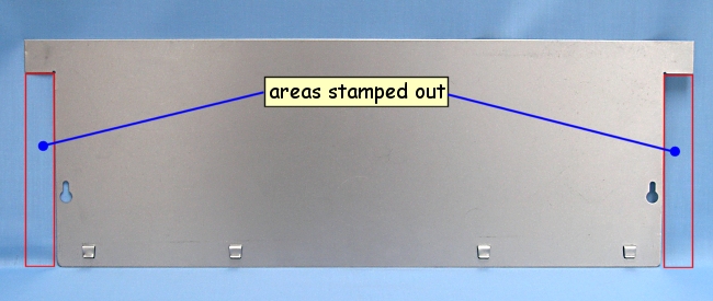
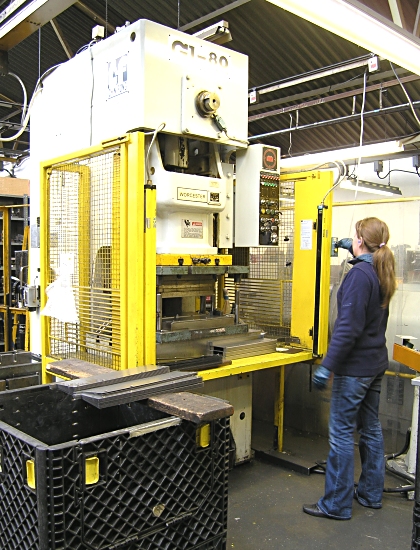
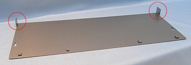
presswork
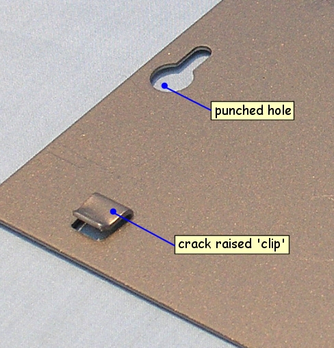
Pre-cut blanks of mild steel sheet are profile cut , punched and crack raised in one power press operation to form the part finished component. component is then transferred to a second press for completion of stages 2 & 3.
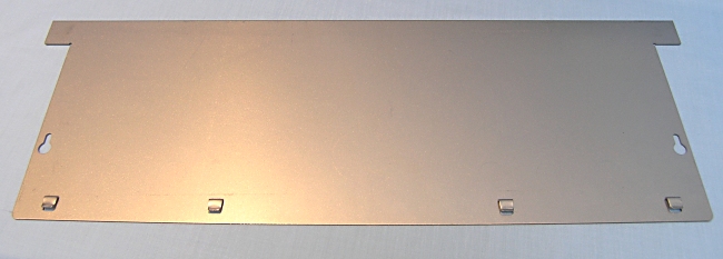
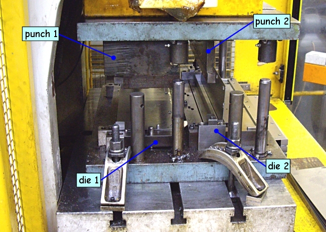
Stages 2 and 3 of manufacturing the electrical enclosure involve bending the partially completed component into shape using a manually operated 80 ton power press. Both stages are carried out during one action of the press. Two press tools are positioned side-by-side in a die set with components being manually transferred from one to the other. In Stage 2 the enclosure ends are bent to 90°. Stage 3 completes the process.
Batches of completed components are then sent for application of a powder coated finish before being dispatched to the customer.
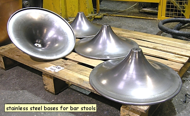
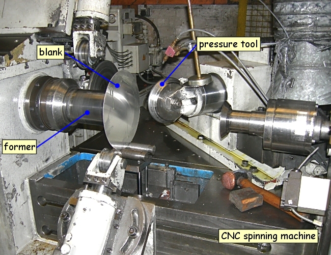
CNC spinning
Circular sheet metal components which are symmetrical about a central axis can be produced by forcing a metal blank onto a rotating former. This process is called Spinning and it is used to manufacture components which cannot readily bepressed or when finishing off pressed components. This shape requires the pressure tool to make a number of passes forcing the material onto the former. The wall thickness of the finished product is the same as that of the blank from which it was made.
When the wall thickness of the blank reduces during the spinning process this is called shear forming.
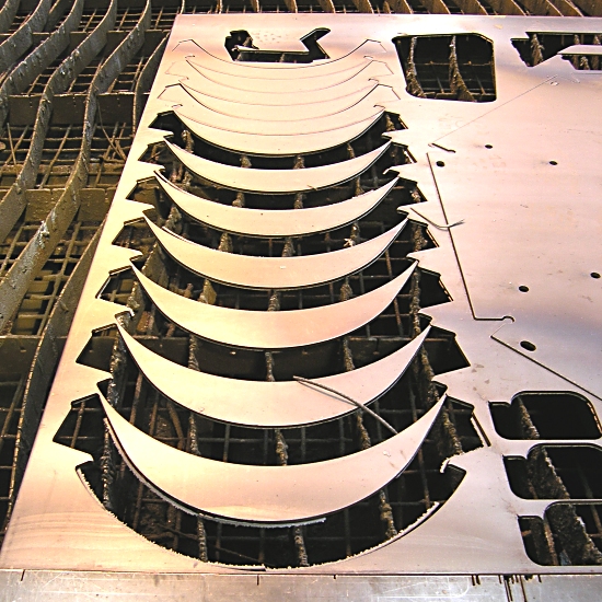
plasma arc cutting
Plasma arc cutting machines are used to cut components accurately, quickly and economically from sheet metal.
The process uses electrically conductive gas to transfer energy from an electrical power source through a plasma-cutting torch to the material being cut. The plasma gases include argon, hydrogen, nitrogen and mixtures, plus air and oxygen. These components have been designed using a 3D computer-aided design (CAD) software program called SolidWorks.
If necessary, once components have been plasma cut they are bent to shape, welded and painted before final assembly.
Waste metal remaining after plasma cutting, is sold for re-processing.
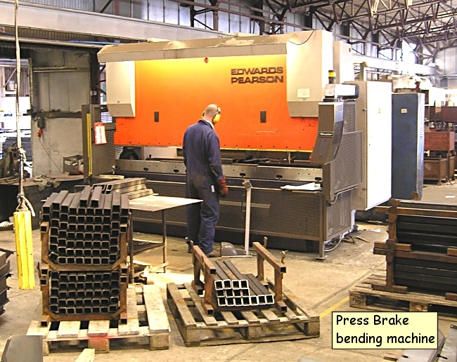
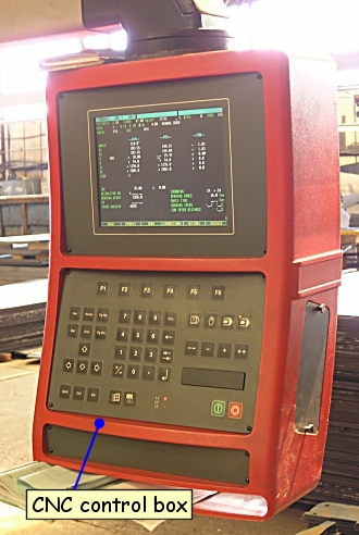
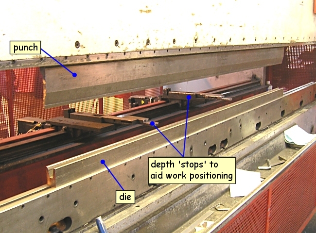
bening sheet metal
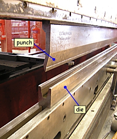
Many components used in the fabrication of Teagle agricultural machinery are plasma cut from sheet steel then bent to shape using a Press Brakebending machine. The floor panel shown in the photo requires five bends to be made in order to complete the finished shape. The process involves positioning the steel sheet between a punch and V-shaped die. The punch then moves down into the die forcing the sheet to bend. A series of bends are programmed and saved into the Press Brake machine's computer. This allows batches of identical components to be manufactured in quick succession.
Machine stops move into position as the location of each bend changes. The angle of each bend is controlled by the distance the punch moves into the die and the cross-section of the die. Sheet metal up to a thickness of 10 mm can be bent cold on this type of machine.
MIG welding
MIG welding (Metal Inert Gas) is one of the methods used to fabricate the side skid for a toppper 8 agricultural grass cutter. A manually programmed robot MIG welding machine is used where a batch of components are clamped onto position of a jig. The jig is then rolled into the welder where a robotic arm with an integrated welding nozzle moves around the component welding parts together. First a dummy run is made to check positioning and movement of the robot arm. Once this is confirmed then the sequence of welds can be saved into the machine's computer. The advantages of using jigs are the that a series of identical components can be accurately and quickly manufactured without the need to employ skilled workers. The robot welder can also operate for hours without the need for rest breaks. Once welding has been completed the finished compoent is released from the jig and another set of components clamped in place in readiness for the next cycle to begin.
drilling: jigs and fixtures
Jigs and fixtures are work holding devices specifically designed for a single or small range of components. Fixtures are used to hold objects in place and clamp them to machines or operating surfaces, so that the object can be worked on, whilst a jig holds the work piece and guides it in relation to a fixed tool or cutter. The machine operator simply clamps the component to the jig and rotates it through 90° in between each drilling operation.
Jigs and fixtures are very common in the batch production of manufactured goods. They allow accurate and fast repeatability of drilling, cutting and shaping operations. This helps reduce production costs by ensuring consistent quality of manufacture, increasing speed of production and by reducing the need for highly skilled staff.
Use of jigs and fixtures can improve safety in the workplace and increase the working life of cutting tools by preventing or reducing the instances of improper machining techniques by machinists.
sheet metal punching
For components requiring a series of holes to be cut in them, it is often quicker to punch rather than drill. The video and animation show holes being punched in 12mm mild steel plate. This operation is carried out on a hydraulic press using a hardened steel punch and die set.
sheet metal punching
For components requiring a series of holes to be cut in them, it is often quicker to punch rather than drill. The video and animation show holes being punched in 12mm mild steel plate. This operation is carried out on a hydraulic press using a hardened steel punch and die set.
Related discussions on The Student Room
- HNC Maths U2 A1 2D »
- Hnc maths »
- Material Selection for Tents »
- Sample digestion method in food testing »
- how is ethyl ethanoate manufactured industrially »
- Hnc electrical engineering maths question »
- Hypothesis Testing »
- Quality/Manufacturing Eng vs Mech Eng »
- hypothesis Testing with only > Mean side of z table »
- Airbus Global Graduate Programme 2023 (for 2024 entry) »
Comments
No comments have yet been made